This is my first post on operating system internals (using Linux as an example) with most of the future posts on this topic to be focused on memory management and device drivers.
This post, I'll discuss how segmentation works in Linux (x86) and how Global Descriptor Tables (GDTs) are used for memory management. These are the basic building blocks of memory management in Linux, with similarities to a lot of other operating systems.
The 8086 microprocessor has been one of the most widely used 16-bit microprocessors in computing history. Several design decisions related to the x86 instruction set architecture can be traced back to the 8086 (not to mention it is one of the reasons why several ugly software hacks have been developed for backward compatibility purposes).
One unique feature of the 8086 was that it had 20 address lines, the address bus being multiplexed with the 16-bit data bus. This means that it could access a total of 220 bytes = 1 MB of memory. However, being a 16-bit processor, the 8086 has a Program Counter (PC) register of size 16 bits. If one of these registers were used to address memory, it would restrict the total amount of addressable memory to just 64 KB.
This is where segmentation comes in. The entire memory could contain a number of "segments" or pieces of memory, each segment of size 64 KB. Programs were free to use these segments as they desired - for example, one segment could be used to hold the code of a program and the other to hold data.
The 8086 has a Code Segment (CS) register which holds the base address of the currently used segment. The value held in it is called the Segment Selector. Addresses are specified as logical addresses of the form
This post, I'll discuss how segmentation works in Linux (x86) and how Global Descriptor Tables (GDTs) are used for memory management. These are the basic building blocks of memory management in Linux, with similarities to a lot of other operating systems.
The 8086 microprocessor has been one of the most widely used 16-bit microprocessors in computing history. Several design decisions related to the x86 instruction set architecture can be traced back to the 8086 (not to mention it is one of the reasons why several ugly software hacks have been developed for backward compatibility purposes).
One unique feature of the 8086 was that it had 20 address lines, the address bus being multiplexed with the 16-bit data bus. This means that it could access a total of 220 bytes = 1 MB of memory. However, being a 16-bit processor, the 8086 has a Program Counter (PC) register of size 16 bits. If one of these registers were used to address memory, it would restrict the total amount of addressable memory to just 64 KB.
This is where segmentation comes in. The entire memory could contain a number of "segments" or pieces of memory, each segment of size 64 KB. Programs were free to use these segments as they desired - for example, one segment could be used to hold the code of a program and the other to hold data.
The 8086 has a Code Segment (CS) register which holds the base address of the currently used segment. The value held in it is called the Segment Selector. Addresses are specified as logical addresses of the form
Segment Selector : Segment Offset
Segment Selector is the value held in CS, while Segment Offset is the value held in PC. PC thus specifies the offset within a segment which can range from 0-65535 bytes. This logical address is converted to a physical address - an address referring to an actual location in system memory - before being used to address memory.
The address bus is 20 bits wide though, which means we need to give it a 20-bit address. To achieve this, the logical address is converted as follows into a linear address:
Protected mode
The address bus is 20 bits wide though, which means we need to give it a 20-bit address. To achieve this, the logical address is converted as follows into a linear address:
(Segment Selector x 16) + Segment Offset
which involves shifting the Segment Selector by 4 bits to the left and adding the offset to it. The base address of any segment thus always has its lowermost 4 bits set to 0.
Protected mode
The above applies in real mode, which is the CPU mode in which a lot of CPUs begin operation. The linear address in this case is same as the corresponding physical address, and is used to access memory.
There are several problems with operation in real mode - no memory protection as any program can access any portion of memory, even that belonging to other programs; there is no support for multitasking and any program can execute any CPU instruction which may lead to unintended consequences (for example, a program bringing the whole system to a halt).
This is why protected mode was introduced by Intel with the 80286 microprocessor. It is supported by all x86 compatible CPUs and provides support for CPU privilege levels, virtual memory, paging and memory protection - among other features.
Protected mode (or p-mode, as it is often called) does not use segmentation in the way described above. It uses a level of in-direction, requiring the setting up of Global Descriptor Tables before any memory access is made in this mode. The GDTs are used for enforcing segment size limits and access rights among other things. One enters into p-mode from real mode by setting bit 0 of the cr0 register to 1 followed by performing a far jump to clear the prefetch queue.
Global Descriptor Table
In p-mode, the segment selector contained in the segment registers consists of 3 parts:

Protected mode (or p-mode, as it is often called) does not use segmentation in the way described above. It uses a level of in-direction, requiring the setting up of Global Descriptor Tables before any memory access is made in this mode. The GDTs are used for enforcing segment size limits and access rights among other things. One enters into p-mode from real mode by setting bit 0 of the cr0 register to 1 followed by performing a far jump to clear the prefetch queue.
Global Descriptor Table
In p-mode, the segment selector contained in the segment registers consists of 3 parts:
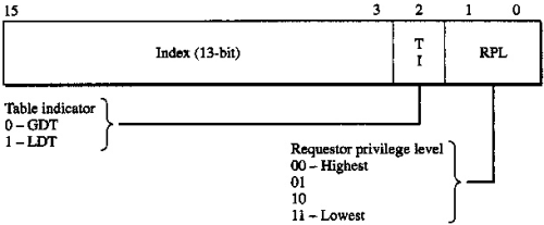
- index, which is an index into the GDT and thus points to an entry of the GDT called a segment descriptor.
- table indicator, which indicates whether the selector points to a GDT or an LDT (Local Descriptor Table, more on this later).
- requestor privilege level (RPL), which is the privilege level of the CPU when the selector is loaded.
The CPU gets the address and size of the GDT from the gdtr register which is 48 bits long. The lower 16 bits of gdtr specify the size of the table while the rest of the bits give the base address of the table in memory. It can be loaded by using the lgdt instruction passing in the address of a 48-bit in-memory structure containing the limit and size.
This means that the size of a GDT can be 216 bytes. Each entry in the GDT is of length 8 bytes, limiting the total number of entries in the table to 8192.
Each entry in the table, or each segment descriptor contains information about one segment and has the following structure:
Shadow Registers
You'd think whenever a memory access is made, the system would have to access the memory location containing the GDT and look up the corresponding segment descriptor. That is not the case - it would slow down processing significantly. Each segment selector register has an accompanying shadow register which is not exposed to the user and is non-programmable.
Whenever a segment selector is loaded in one of the registers, the corresponding segment descriptor is accessed from the GDT in memory and loaded into this shadow register. Future references to the segment descriptor will use the contents of this shadow register and not access memory each time.
Segmentation and GDTs in Linux
Linux uses segmentation in a very limited way. Most modern OSes use only paging for several reasons:
Each entry in the table, or each segment descriptor contains information about one segment and has the following structure:
- limit (0:15) - bits 0 to 15 of the segment limit which is a 20-bit value indicating the maximum segment size
- base (16:39) - bits 0 to 24 of the segment base i.e. the starting address of the segment
- AC (40) - accessed bit. Set to 1 by CPU when segment is accessed
- RW (41) - read/write bit.
- for code segments, this specifies if the code segment can be read. Write access is always disabled for code segments
- for data segments, this specifies if the data segment can be written to. Read access is always enabled for data segments
- DC (42) - direction/conforming bit.
- for data segments, it is the direction bit. 0 means the segment grows up, 1 means it grows down.
- for code segments, it is the conforming bit. If set to 1, the segment can be executed from an equal or lower privilege level. If set to 0, the segment can only be executed from the level set in DPL.
- Ex (43) - if 1, this is a code segment; else, a data segment
- Descriptor (44) - if 0, this is a system descriptor that is used to store critical data structures; else this is a normal code/data descriptor
- DPL (45:46) - 2 bits specifying the descriptor privilege level of this segment, used to control access to the segment
- Pr (47) - present bit, must be 1 for all valid selectors
- limit (48:51) - bits 16 to 19 of the limit
- 52:53 - always set to 0
- Sz (54) - size bit. If 0, this defines a 16-bit p-mode segment. Else, it defines a 32-bit p-mode segment.
- Gr (55) - granularity bit. If 0, limit is in 1 byte blocks. Else, it is in 4 KB blocks.
- base (56:63) - bits 24 to 31 of the segment base
Bits 0 to 13 of a segment selector specify the index, as described above. This is an index into the GDT, which means specifying 0 for the index will access the first segment descriptor, 1 will access the second descriptor and so on. The index is multiplied by 8 to get the address of the descriptor in the table.
When entering p-mode, there must be at-least one null segment (a segment with everything set to 0), one code segment and one data segment. The process of loading a new GDT is completed by loading CS followed by DS and other segment selectors. CS can be loaded by a far jump. Here's a sample code:
init_gdt_load:
     lgdt [gdtr]
     jmp 0x08:finish_gdt_load

finish_gdt_load:
     mov ax, 0x10
     mov ds, ax
     mov ss, ax
     mov es, ax
     mov fs, ax
     mov ss, ax
When doing jmp 0x08:finish_gdt_load, we give 0x08 = 0000000000001000 for CS. The top 13 bits equate to 1 which when multiplied by 8 gives 8 - meaning we take the descriptor located at 8 bytes from the start of the table (which would have to be a code segment descriptor here).

Conversion of a logical address to a linear address by segmentation
Shadow Registers
You'd think whenever a memory access is made, the system would have to access the memory location containing the GDT and look up the corresponding segment descriptor. That is not the case - it would slow down processing significantly. Each segment selector register has an accompanying shadow register which is not exposed to the user and is non-programmable.
Whenever a segment selector is loaded in one of the registers, the corresponding segment descriptor is accessed from the GDT in memory and loaded into this shadow register. Future references to the segment descriptor will use the contents of this shadow register and not access memory each time.
Segmentation and GDTs in Linux
Linux uses segmentation in a very limited way. Most modern OSes use only paging for several reasons:
- One can avoid loading the segment registers every now and then for accesses to different segments
- It avoids the problem of fragmentation
- Segmentation provides only 8192 segments (through the GDT) at any time which might be a hurdle to maximising the use of segments
Linux uses only two privilege levels - 0 (kernel or supervisor mode) and 3 (user mode). Four segments are defined:
- Kernel code segment - 0-4 GB with privilege level 0
- Kernel data segment - 0-4 GB with privilege level 0
- User code segment - 0-4 GB with privilege level 3
- User data segment - 0-4 GB with privilege level 3
This essentially means setting the base of the segment to 0 and the limit to the full 32-bit address space, with the granularity flag set to 1. This is called a flat memory model and offers one big advantage of using segmentation - memory protection using segment sizes and privilege levels - while also using paging.
There are mainly four types of segments used in Linux and hence four major types of segment descriptors:
There are mainly four types of segments used in Linux and hence four major types of segment descriptors:
- Code Segment Descriptor - for a code segment.
- Data Segment Descriptor - for a data segment.
- Task State Segment Descriptor - for a task state segment (TSS) which is used to store the processor register contents and can appear only in the GDT
- Local Descriptor Table Segment Descriptor - for a segment containing a Local Descriptor Table (LDT). This can appear only in the GDT.
There is only one GDT for the whole system. Each process can have its own LDT if it needs to allocate more segments than the ones in the GDT. Similar to the GDT, the size and base address of the LDT are stored in the ldtr register.
Linux uses 32 segment descriptors stored in the cpu_gdt_table array. There is one such array for each CPU. The sizes and addresses of the GDTs are in the cpu_gdt_descr array.
14 of these are null segment descriptors. Often, several segment descriptors describe segments related in some way and need to be accessed together. These null segment descriptors are placed in the table such that the set of descriptors that need to be accessed together can be fetched into the same line of the hardware cache. The remaining 18 descriptors are as follows:
14 of these are null segment descriptors. Often, several segment descriptors describe segments related in some way and need to be accessed together. These null segment descriptors are placed in the table such that the set of descriptors that need to be accessed together can be fetched into the same line of the hardware cache. The remaining 18 descriptors are as follows:
- Two code segments descriptors - for kernel code and user code
- Two data segments descriptors - for kernel data and user data
- One TSS descriptor
- One descriptor describing a segment containing the default LDT
- Five segment descriptors describing segments for PnP BIOS services (used by the BIOS when working with PnP devices)
- Three TLS (Thread Local Storage) segment descriptors.
- One TSS segment descriptor for a segment used to handle double fault exceptions
- Three segment descriptors describing segments used for APM (Advanced Power Management) (used by the BIOS when working with APM devices)
---------------------------------
That ends the (not-so-brief) overview. I've tried my best to keep it as simple as possible while covering all the important aspects. There's lots more to Linux's memory management along with a lot of gory details, which require separate posts in themselves.
It would be great to have your comments about the post, and anything I might have overlooked.
Until next time!
Until next time!

No comments:
Post a Comment